|
|
|
|
|
|
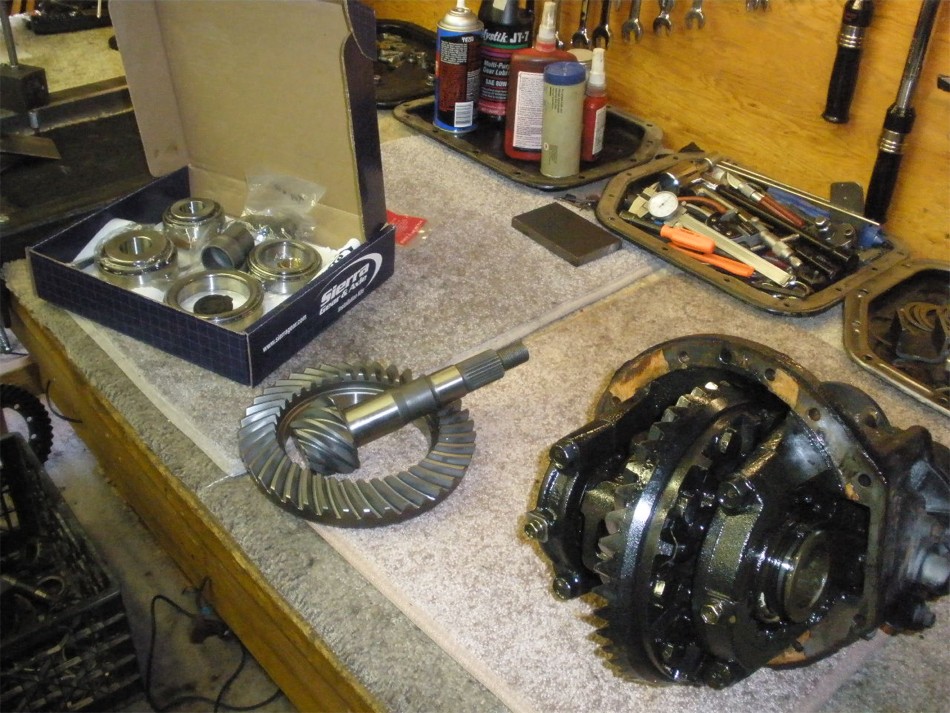
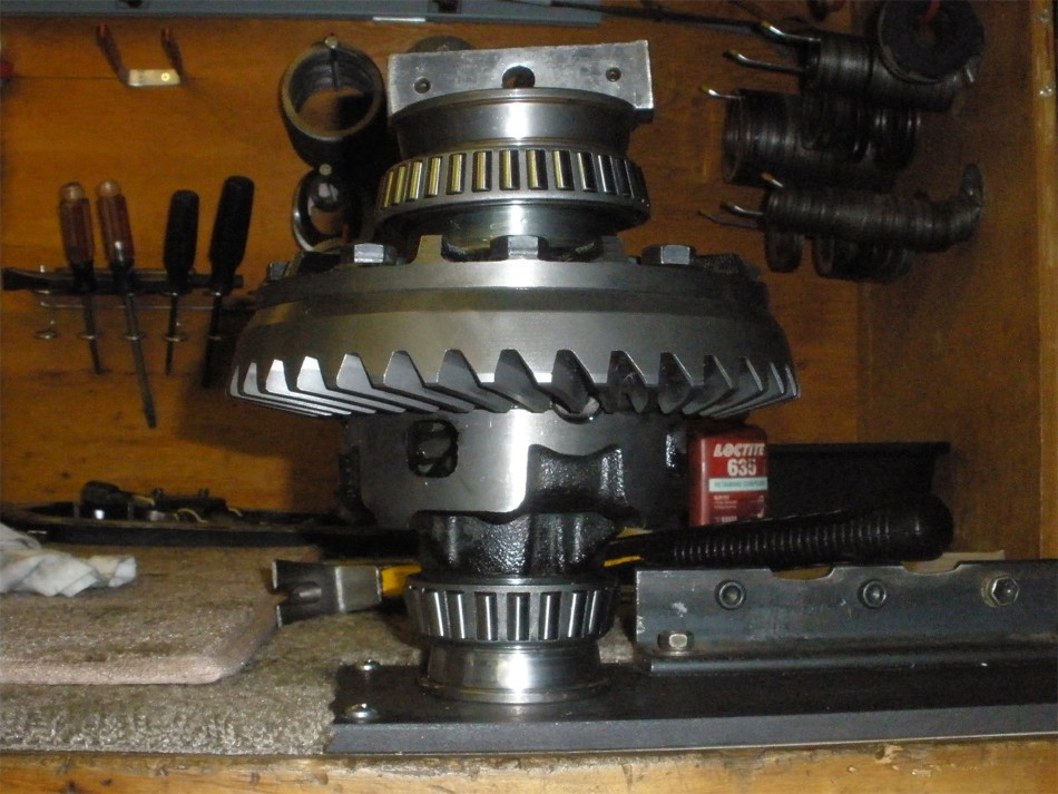
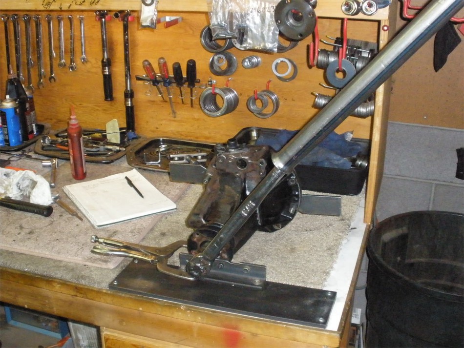
Sierra Gear master install kit with crush sleeve...Sierra ring and pinion(actually "Circle K" gears) and one 8" high-pinion 3rd with the e-motor still attached. |
|
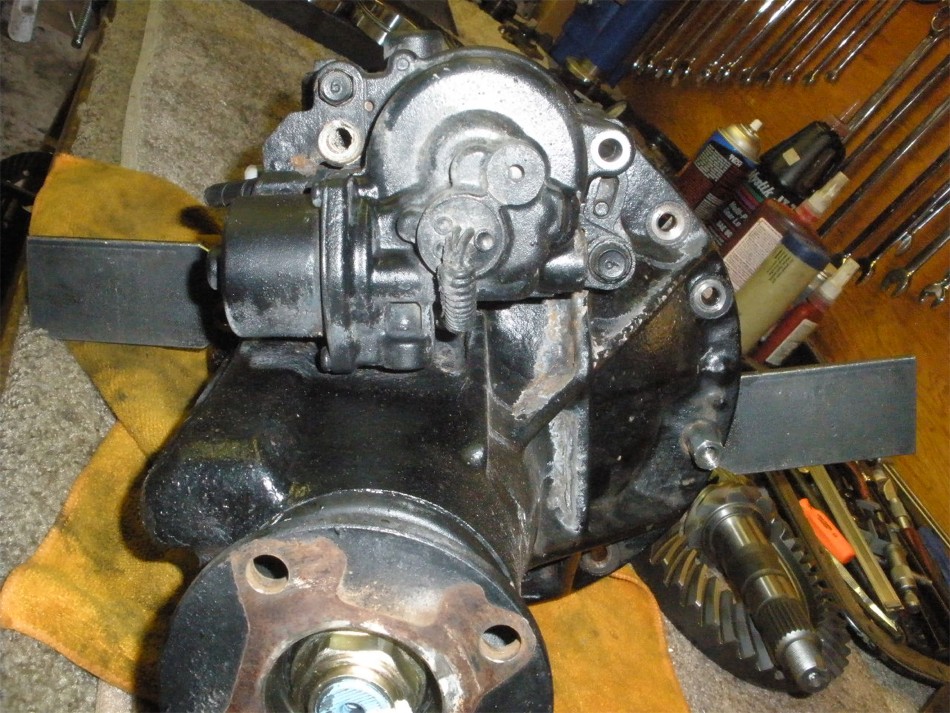
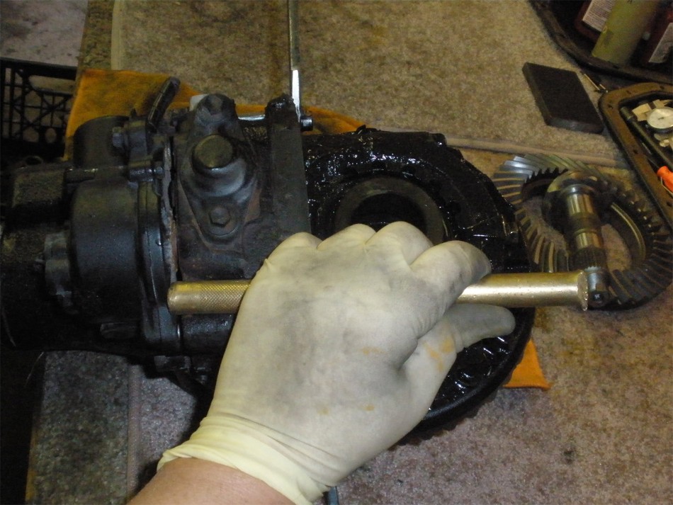
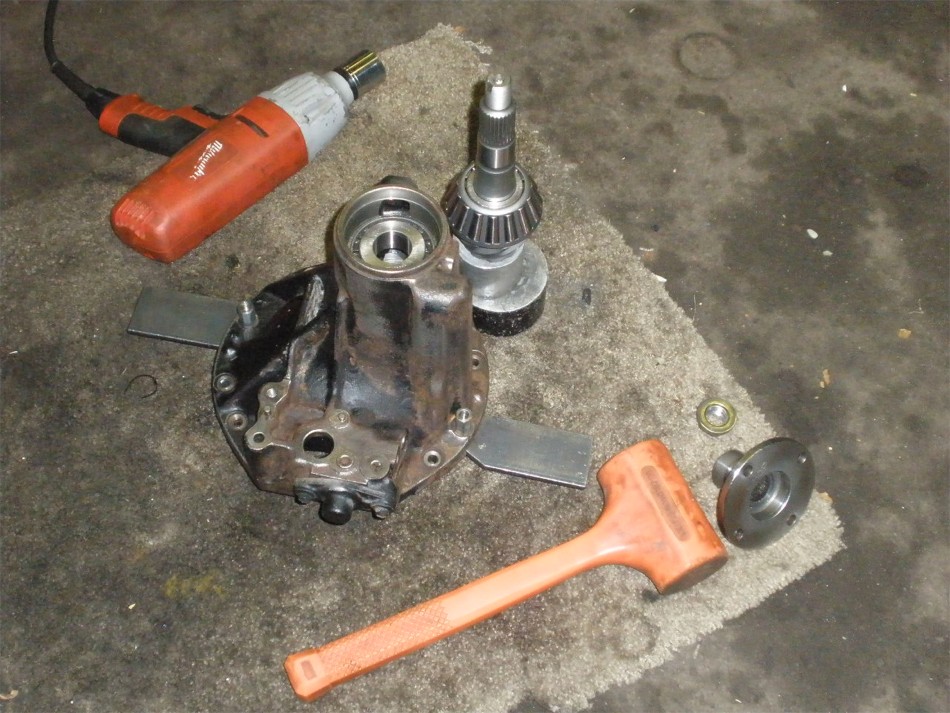
First, to remove the e-motor. |
|
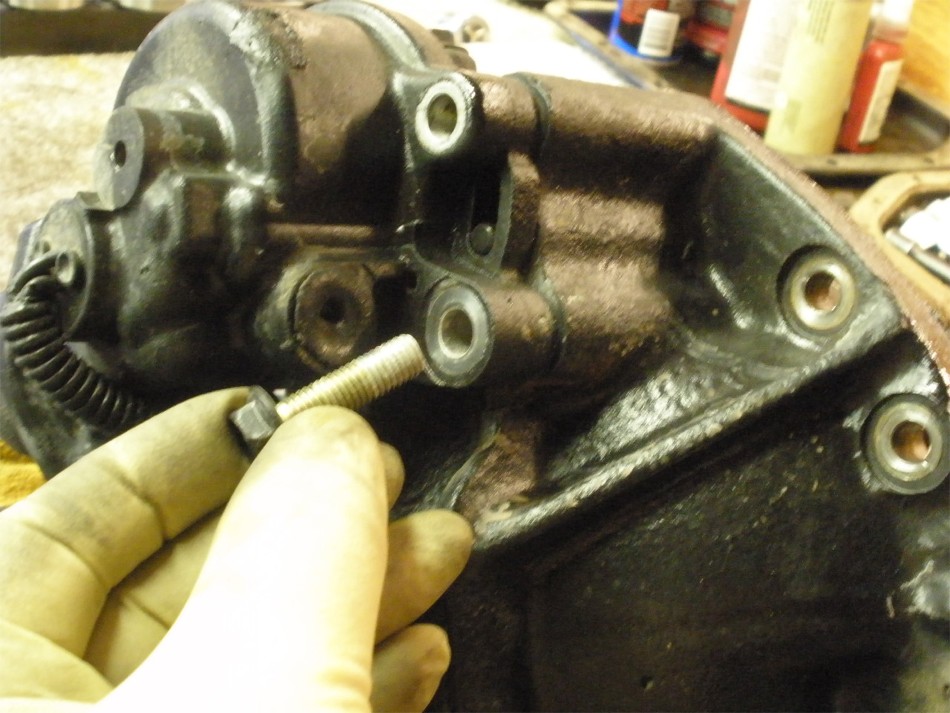
This is the only bolt holding it down. |
|
Bolt comes out... |
|
...and carefully tap the motor off. It might be stuck a little bit but with some taps and jiggling it will come off. |
|
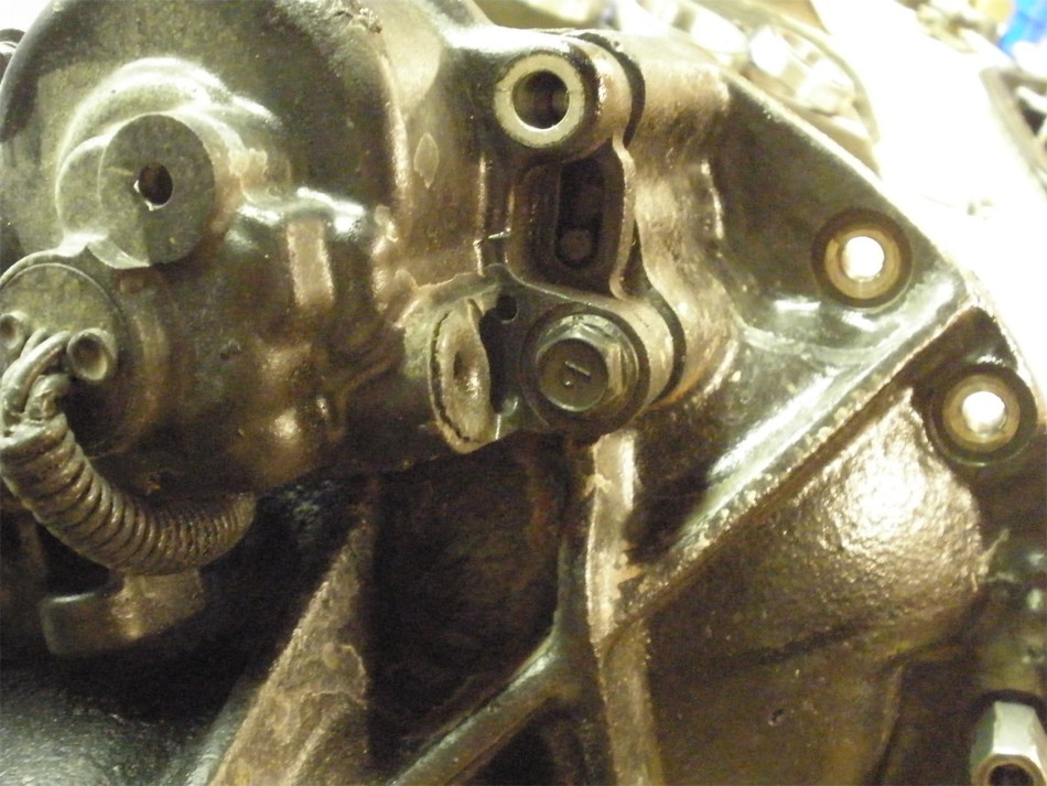
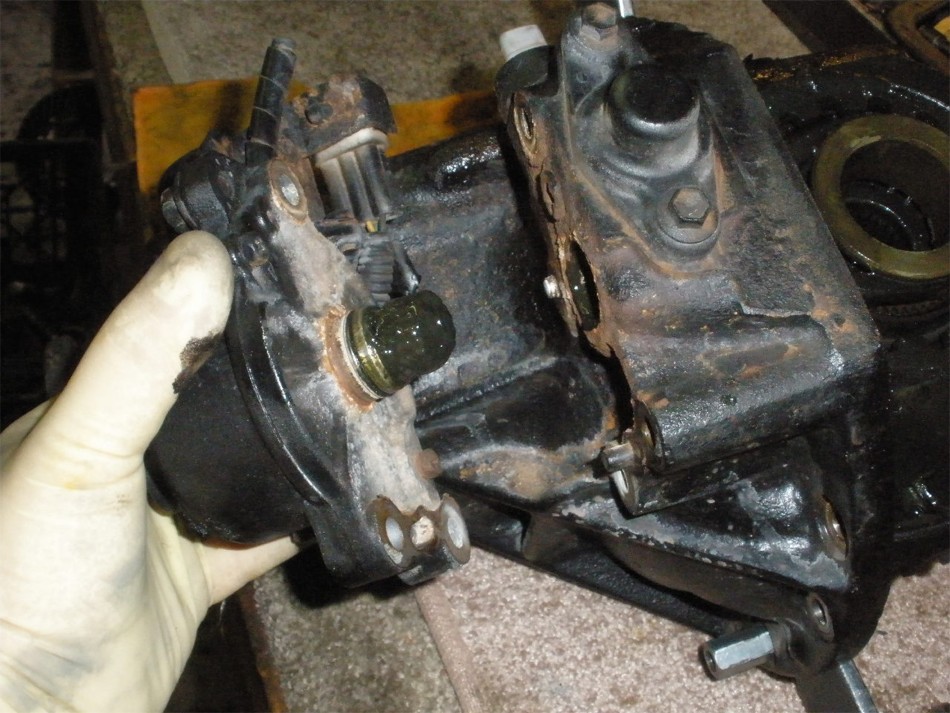
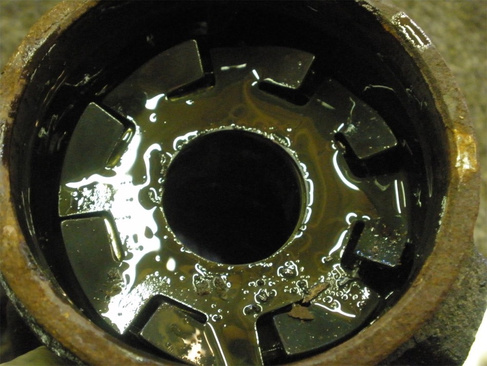
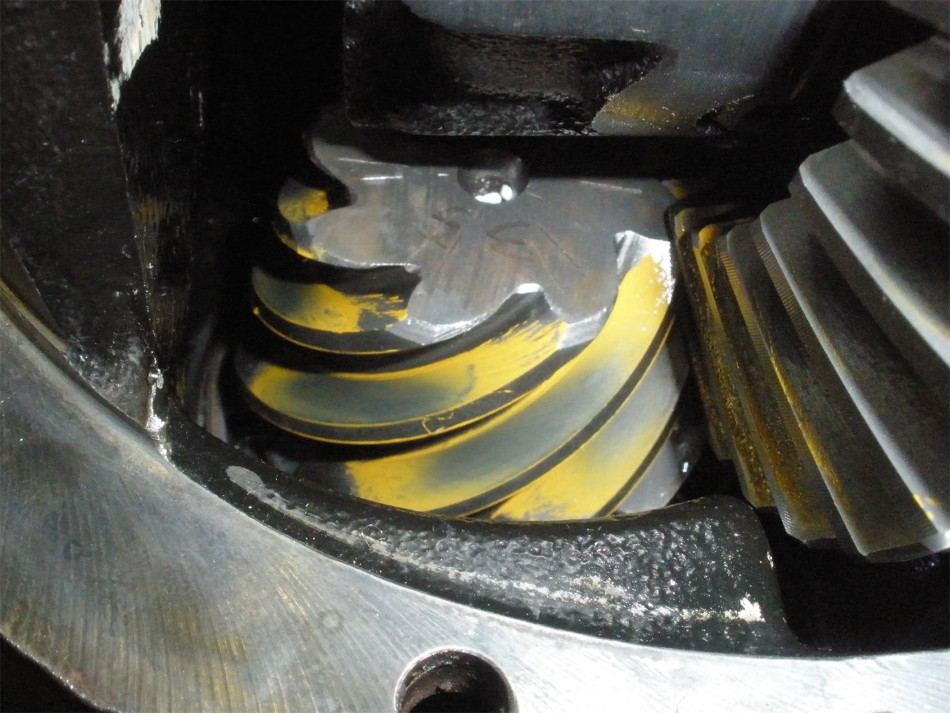
Motor is off. Looks like the knuckle grease worked its way into the gear oil. |
|
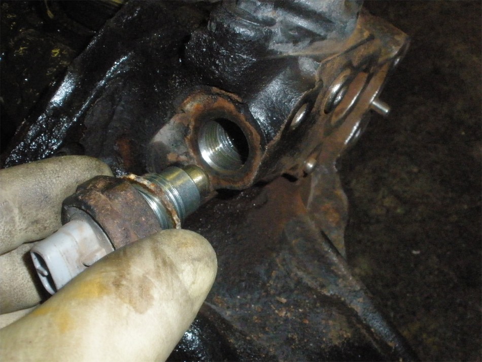
This is the sensor switch that determines when the locking fork has moved to and from being locked. A 27mm or 1 1/16" socket will remove this one.
It has a plastic upper base so it's best to remove this to prevent breakage.
|
|
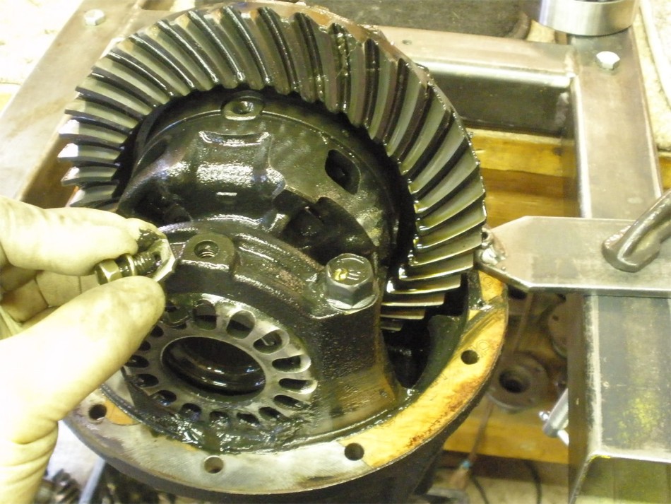
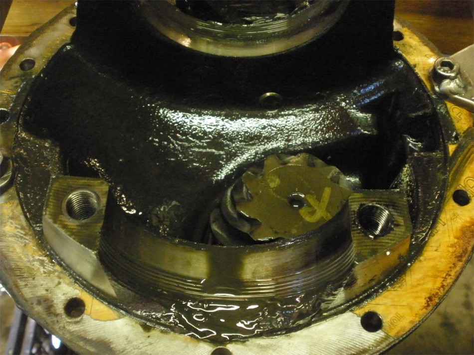
Teardown starts with this lock tab bolt. The grease makes it a little messier but starting fluid works well for me and cleans it nicely. |
|
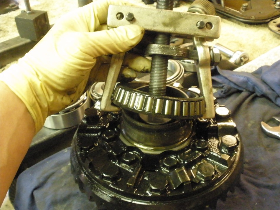
It took almost no effort to remove the large carrier bearing. Sleeve-lock compound will be used on the new one. |
|
The case side bearing took a good effort to remove so no sleeve-lock here. |
|
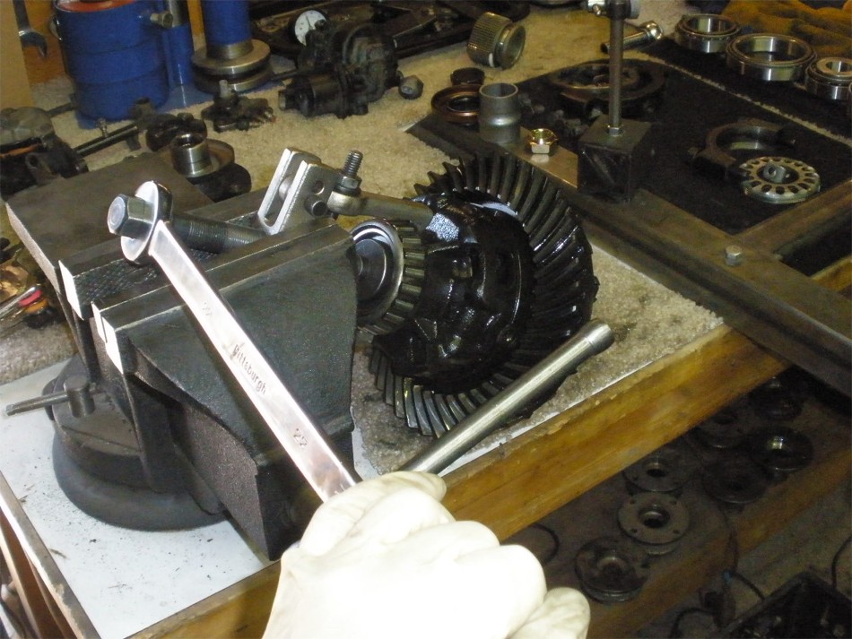
The old 410 ring tapped off just fine with proper persuasion. |
|
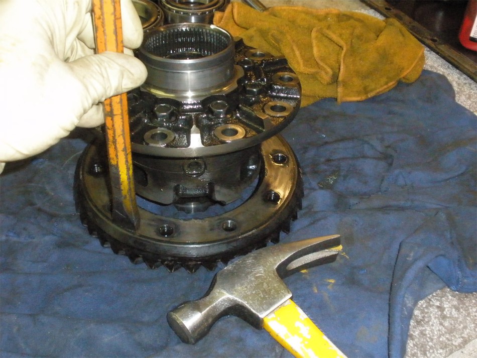
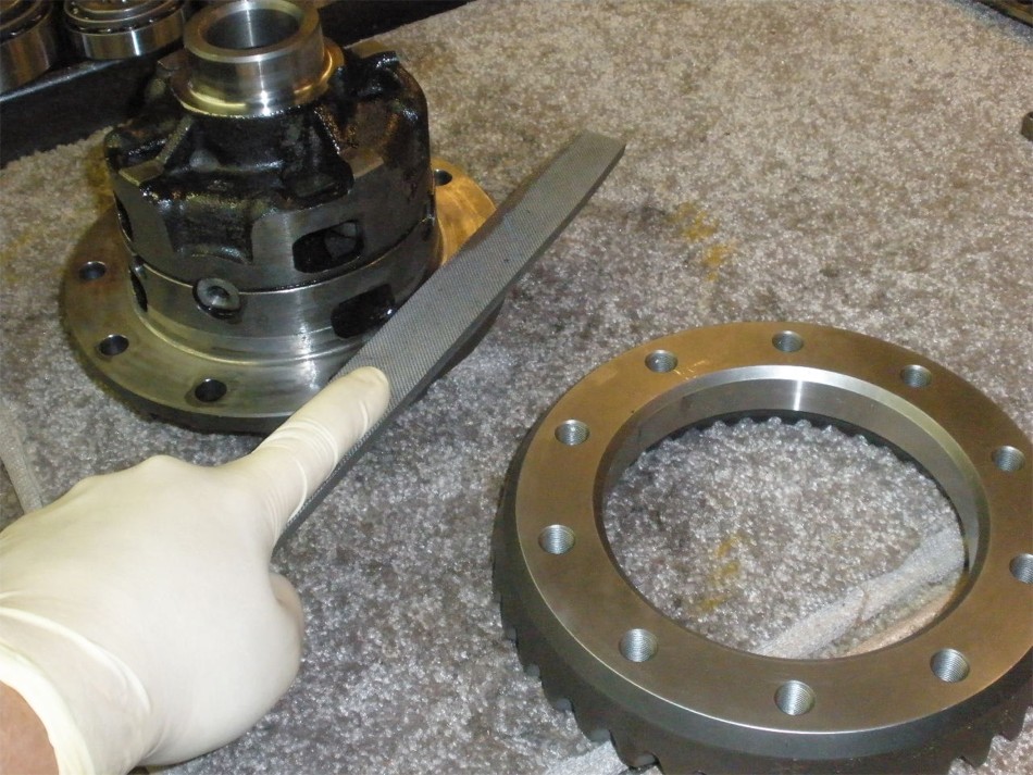
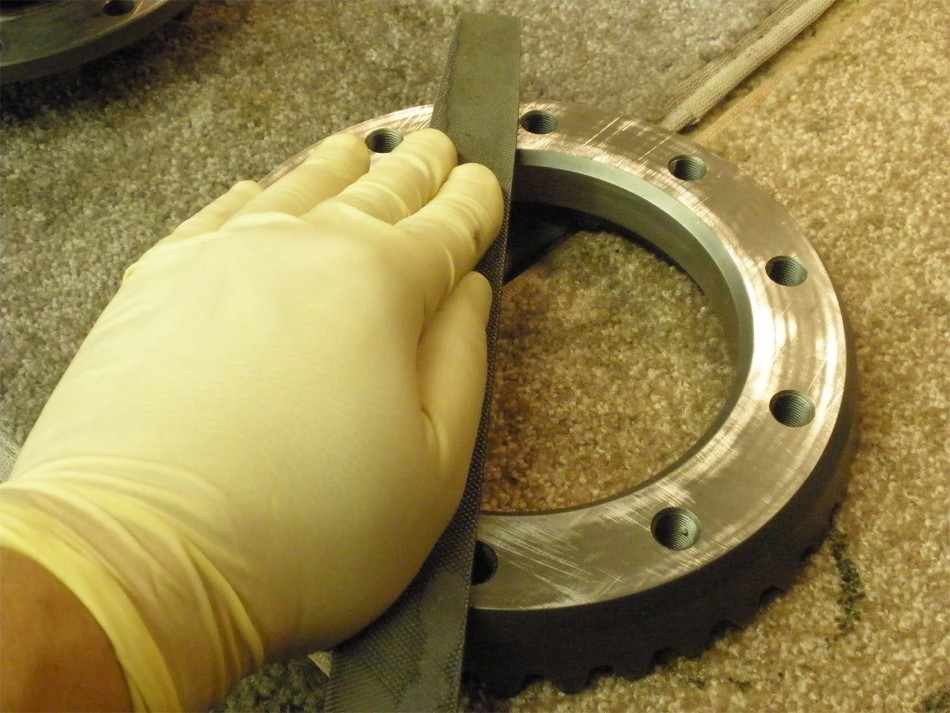
I use a large flat file to check for burrs and high spots. |
|
With this extra rough file and 50 pounds of downward pressure, I am able to make a slight dent in the surface skin. |
|
The ring was a very close fit...slight tapping with the lead filled plastic hammer did the trick. |
|
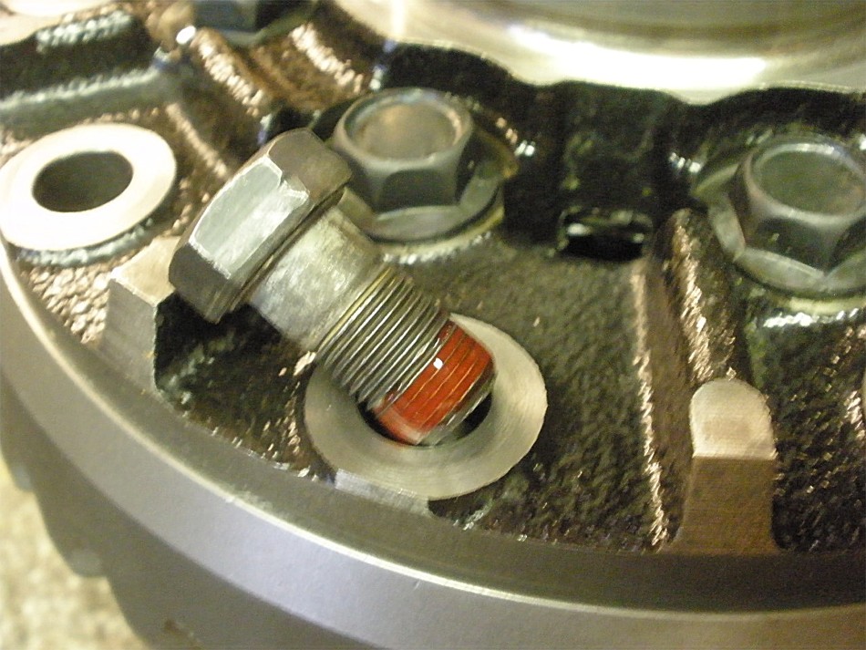
The 10 brand new ring bolts are cleaned and red Loctite applied. |
|
75 ft/lbs on each bolt. |
|
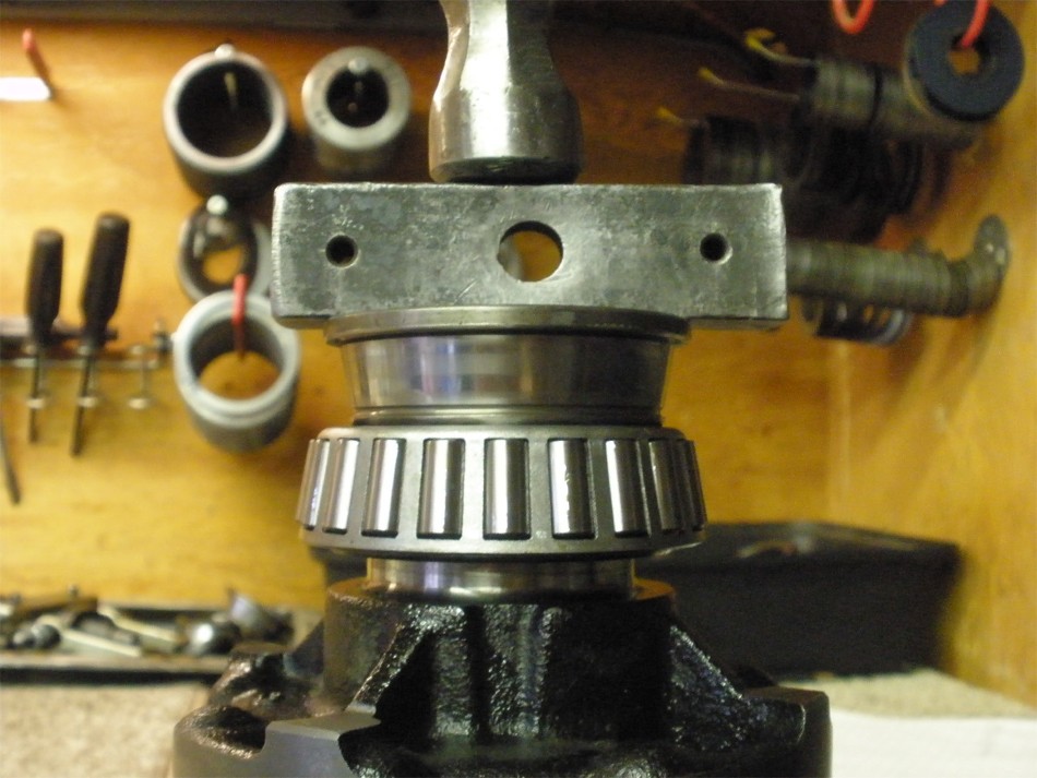
This one tapped on very tight. No press needed when the right spacers are used. |
|
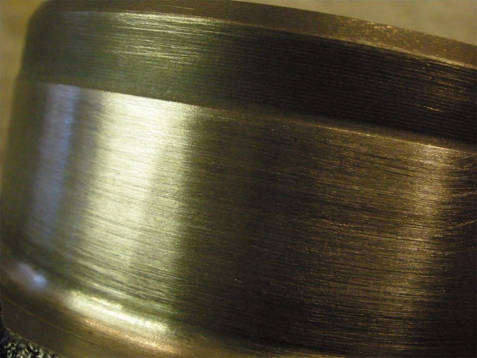
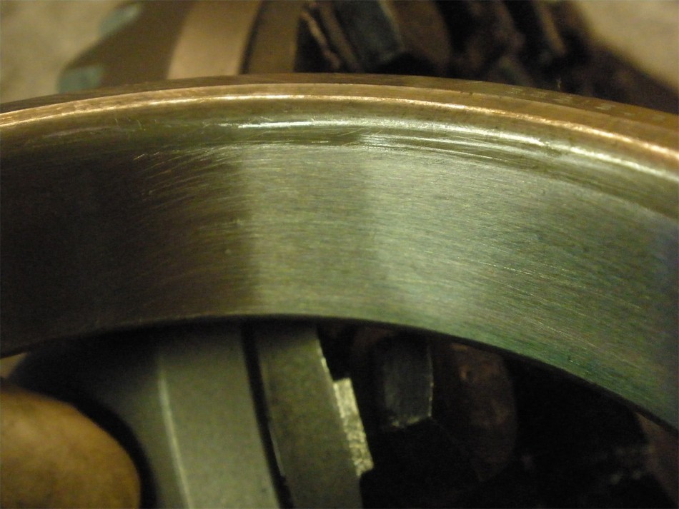
This is after a light sanding(extra rough 60 grade paper) on the ring-side journal. I believe this will help the sleeve lock compound keep a strong grip. |
|
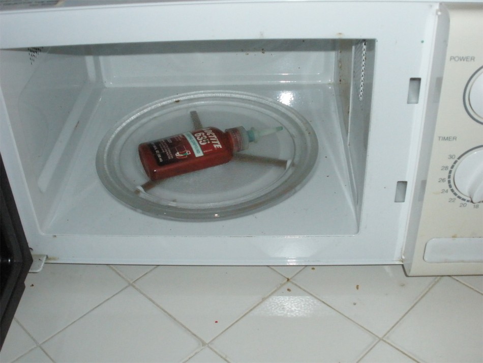
The green compound is extra thick and must be mixed well before use. 5 or 8 seconds on the merry-go-round is enough to heat up and thin out the compound making it easy to shake up. I believe that's the reason others have had bad luck with sleeve-lock/thread-lock is the inability to shake it up properly(in cold weather) and also not cleaning the sleeve surfaces enough. |
|
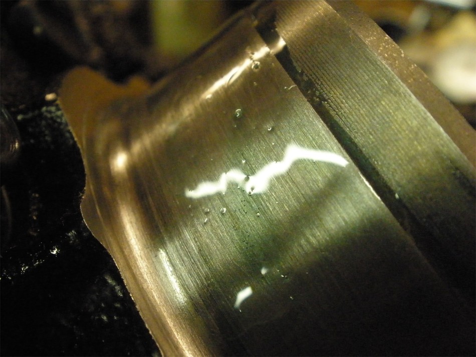
A few drops is applied and smeared into the pores of the material 100% the way around. |
|
Same thing for the related bearing surface. |
|
Now to tap the bearing down and let it set up for 24 to 48 hours. The thick green compound acts like a grease and lets the bearing slide down the journal with relative ease. |
|
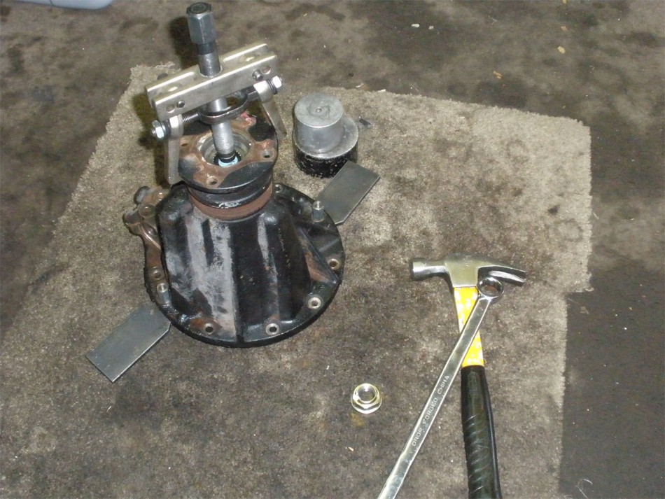
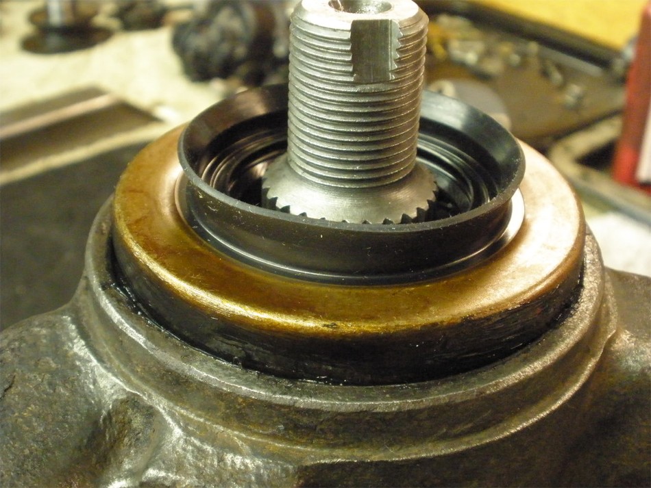
Meanwhile, the flange can be removed. This one was on there good and the puller was needed. |
|
... |
|
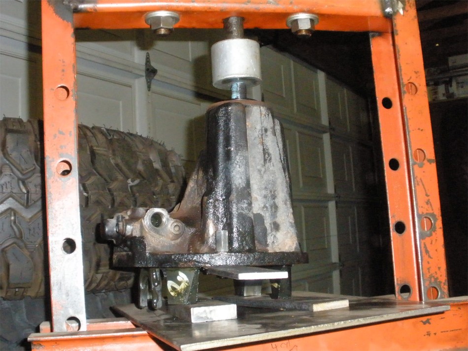
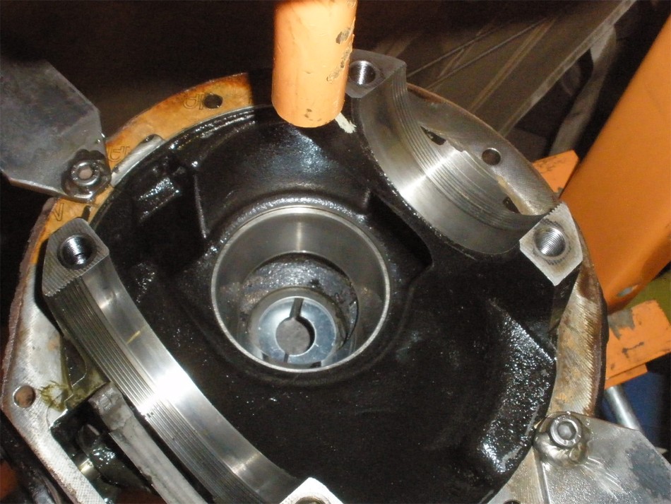
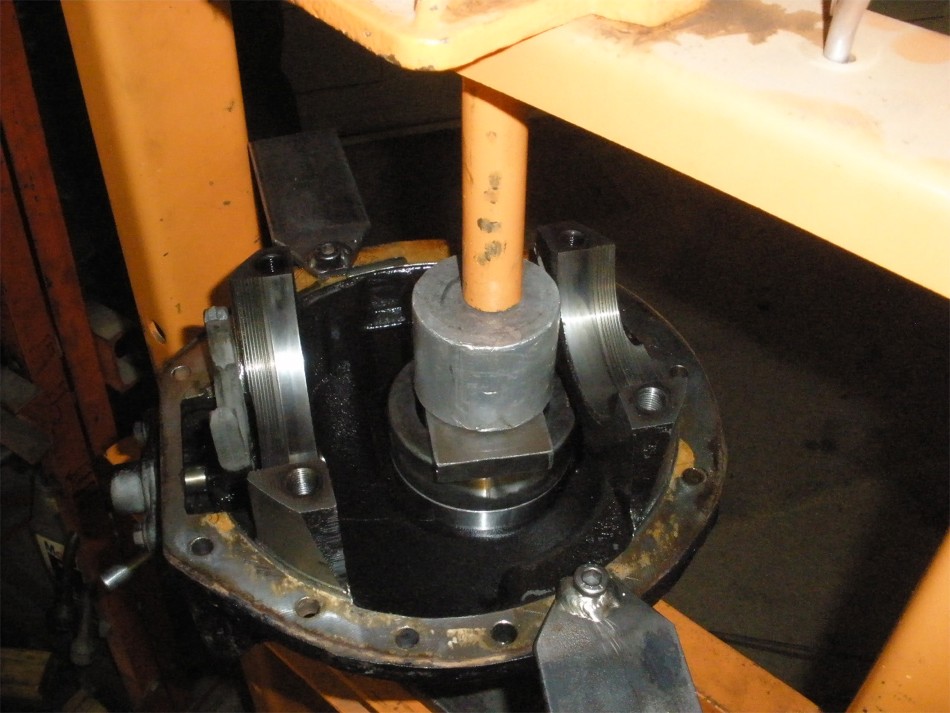
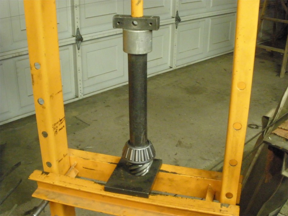
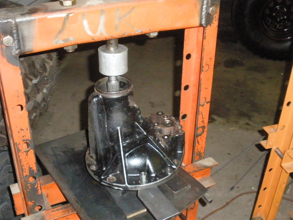
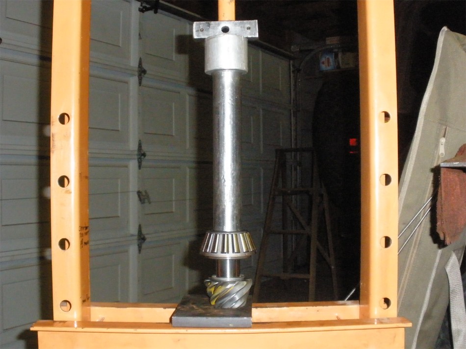
The press eases the pinion out. Notice I have the base up on steel plates so the locking fork is not stressed/damaged. |
|
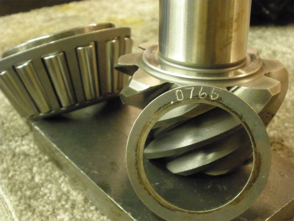
The only thing of any value is the pinion depth shim under the bearing. |
|
Press the old bearing off and save the shim for re-use. |
|
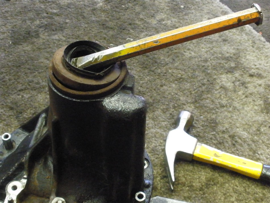
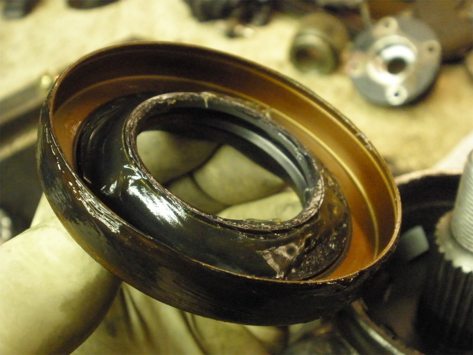
Remove the seal. |
|
Now the oil slinger and outer bearing can be removed. |
|
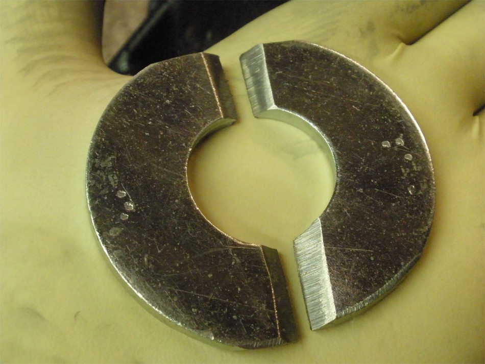
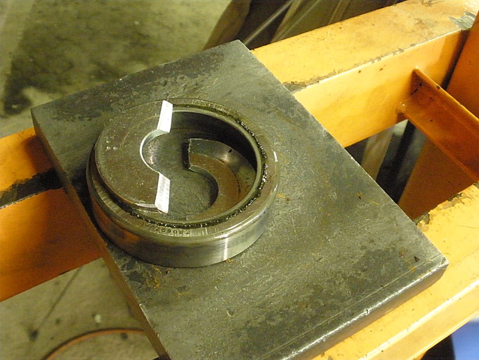
Scott Szymanski, down near Tucson, emailed me this idea. He's accustomed to making his own tools for the industrial differentials he works on. This is just a 2.25" diameter washer cut in 2 and is used to remove the outer pinion race without any damage whatsoever to the oil retainer. |
|
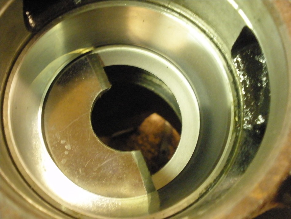
It slips under the race...loose fit but it will do the job. |
|
In the process of flipping the 3rd over onto the press, sometimes the washer halves fall out but done right they will stay in place. Use the grease trick....apply thick grease to the washer's outer edge and that will keep them in place. |
|
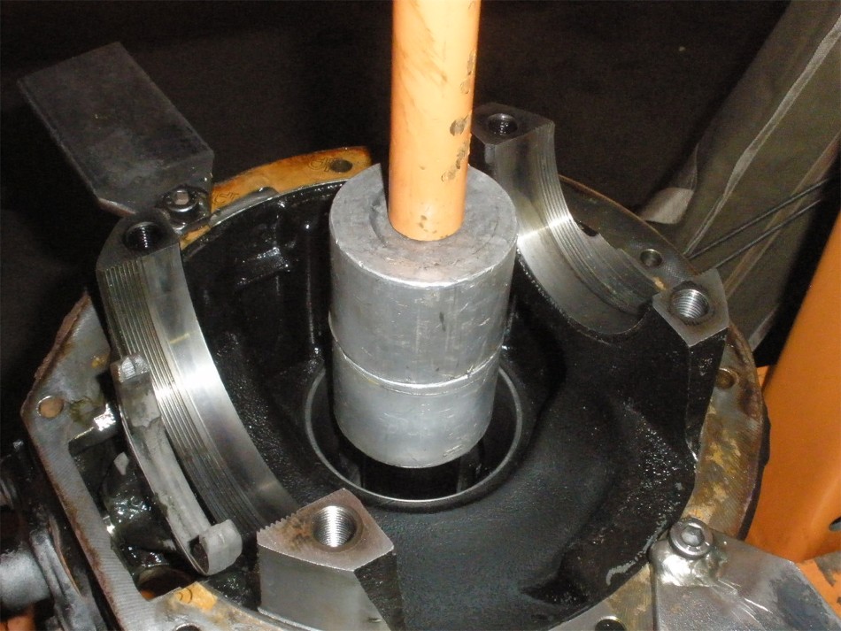
Now find a large diameter socket that will just clear the inside diameter of the oil retainer. |
|
The socket is resting flat on the washers and the aluminum blocks are on top that. |
|
Minimal force is needed to press the race out...out drops the race and the 2 washer halves. |
|
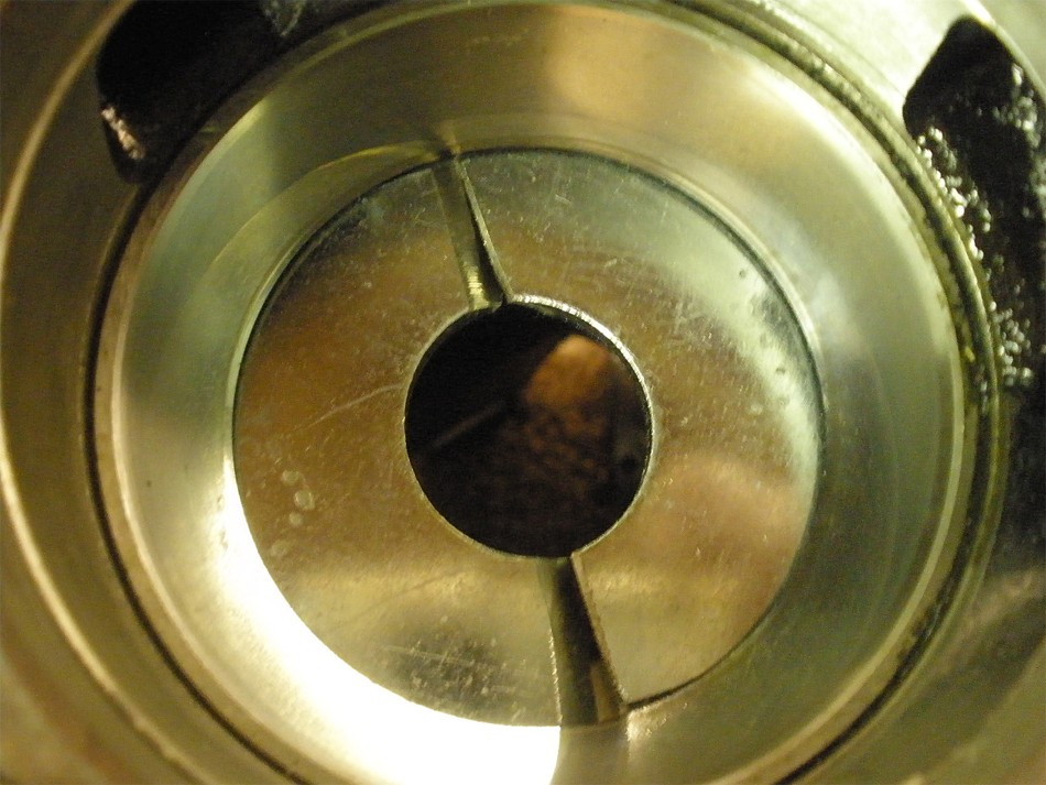
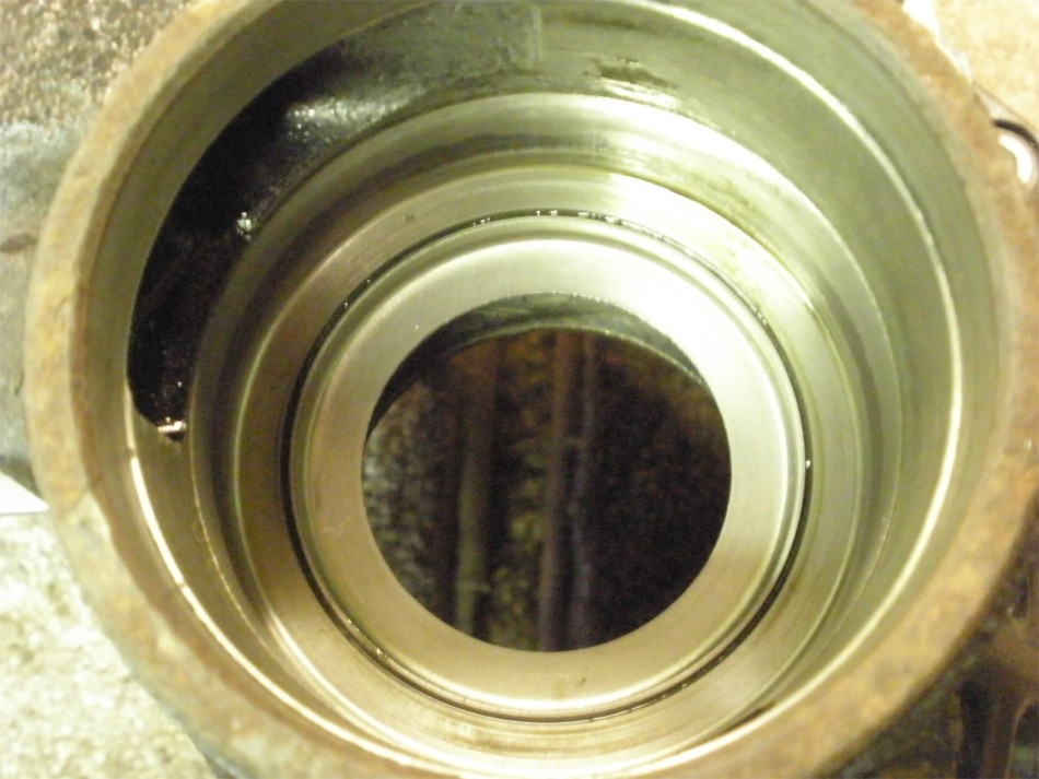
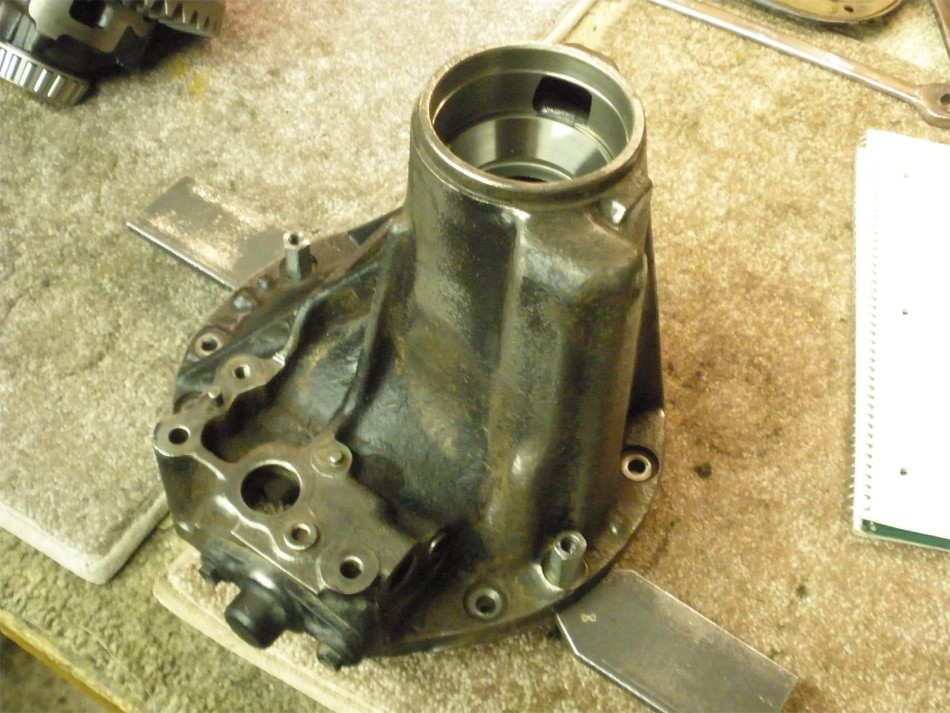
The oil retainer is untouched |
|
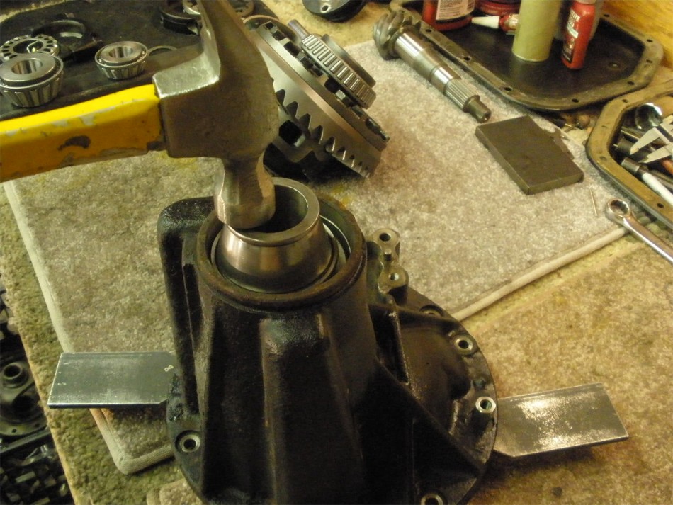
Now to press the large inner race in the hole. |
|
The top race can be pressed but tapping it down is quicker....no damage with the right spacers. |
|
..... |
|
...... |
|
The factory .0765" shim will suffice for the first pattern check. |
|
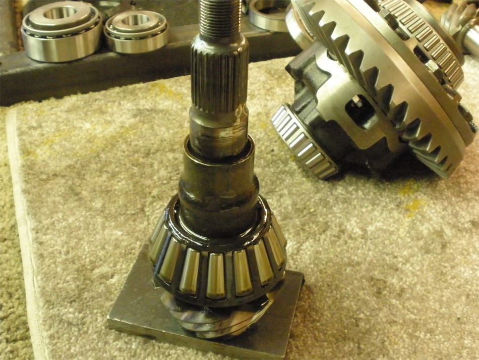
Old shim and new bearing are pressed on. |
|
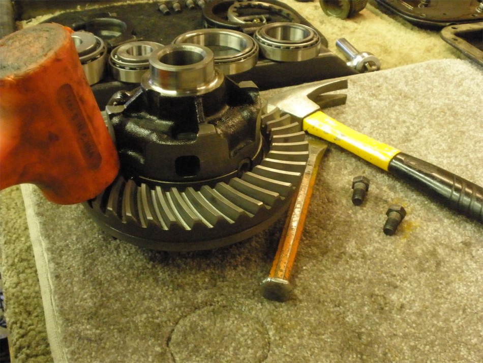
With the pinion spaced up on 2 aluminum blocks, the 3rd can be positioned over the pinion and the flange pounded on with the plastic hammer. |
|
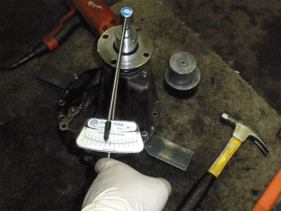
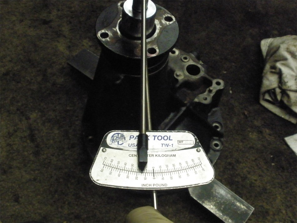
With plenty of gear oil on both bearings, the electric impact will easily snug the nut to the desired amount of PPL. The torque wrench really does get used many times through-out the install. I don't depend on "feel" even though I probably could. |
|
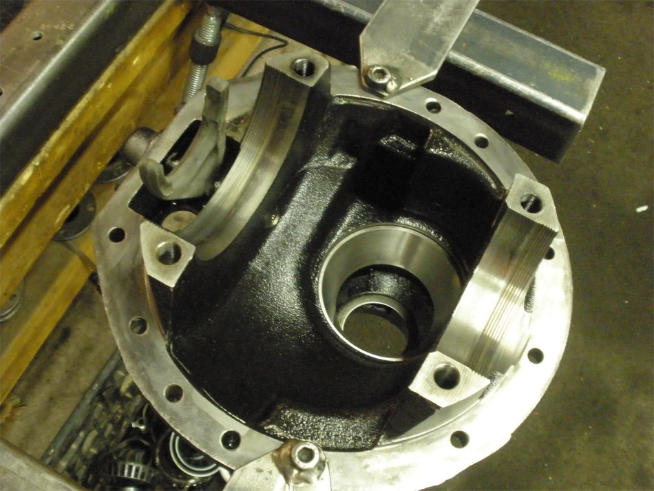
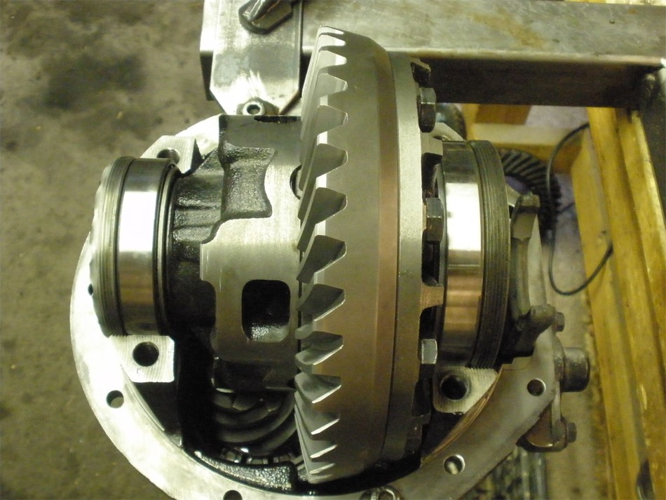
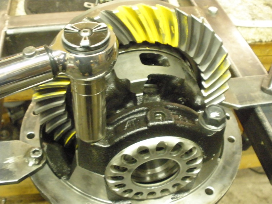
The center case is dropped in place. Spanner adjusting wheels are verified to be in the correct thread. Skipped a few steps but bearing caps are bolted up....backlash is adjusted and some but not all of the CBPL is applied. |
|
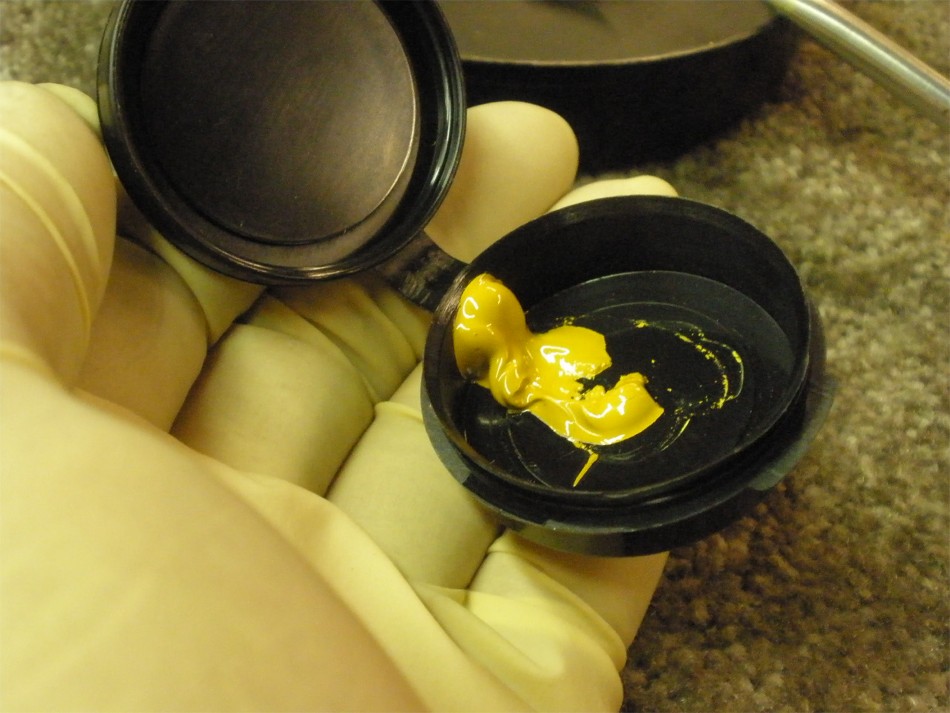
They certainly don't give you too much marking compound. |
|
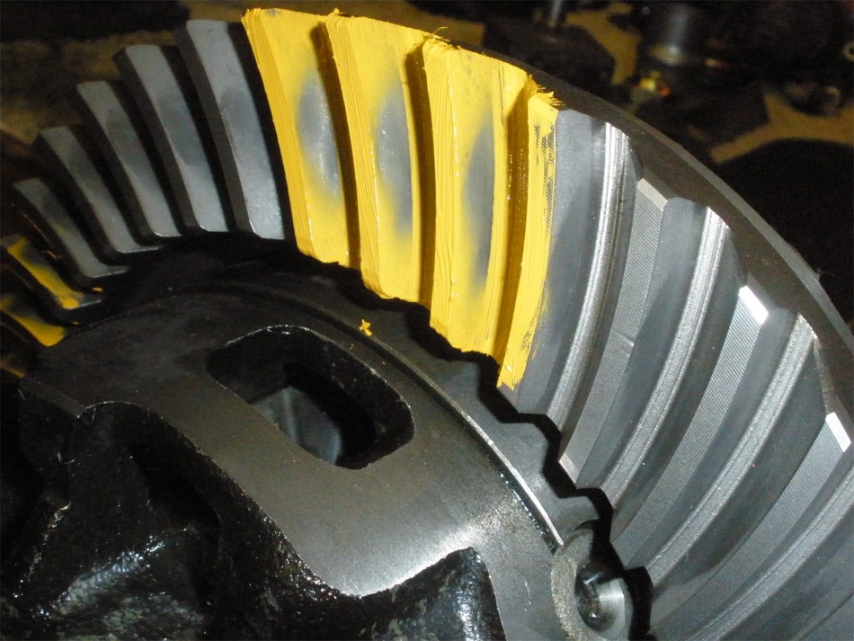
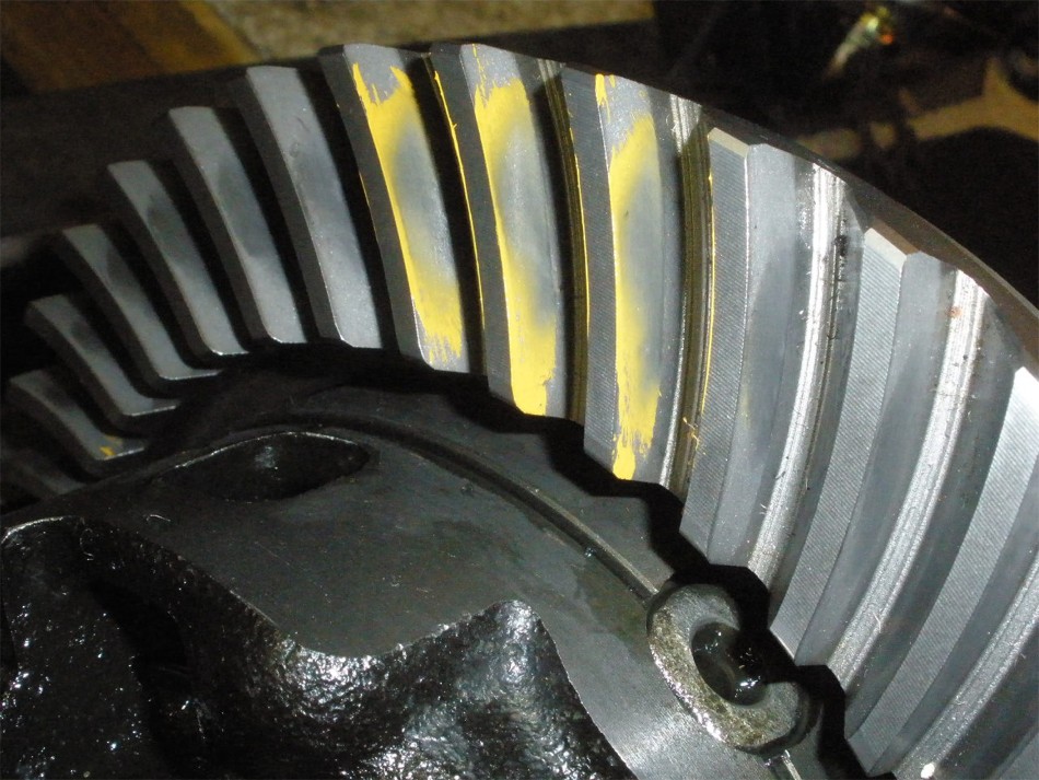
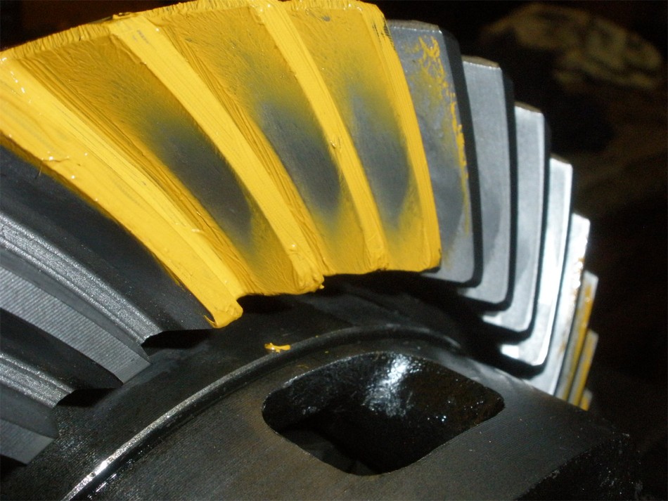
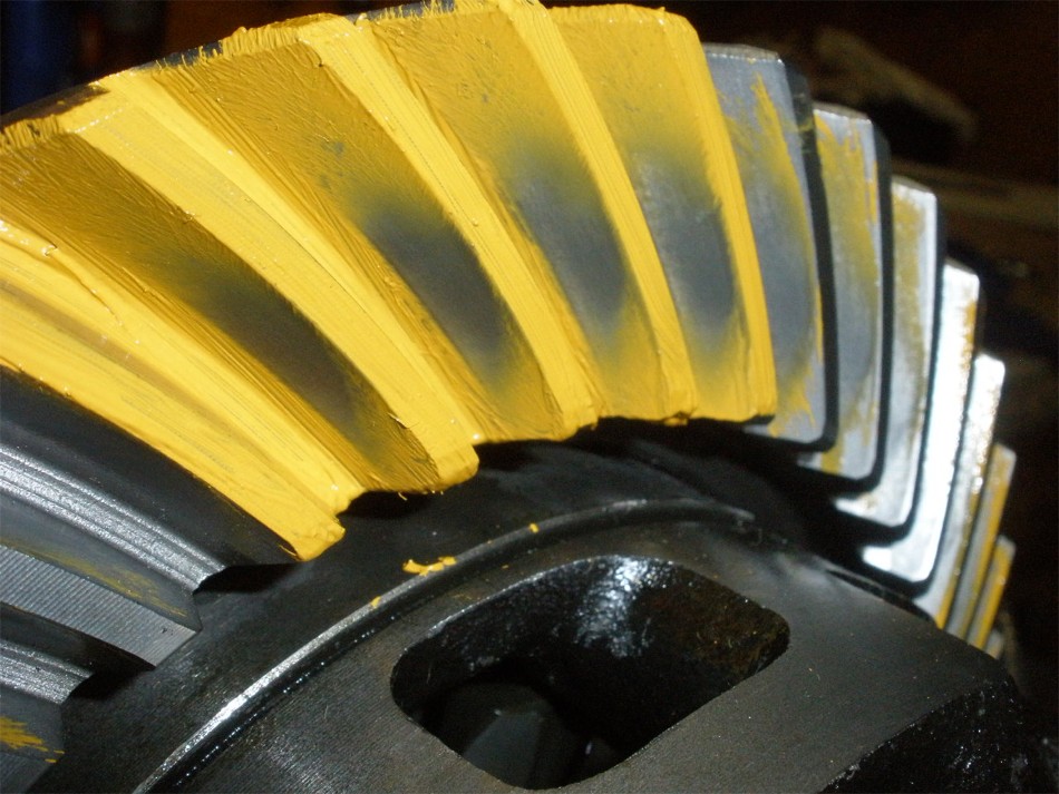
DRIVE---- a little deep. |
|
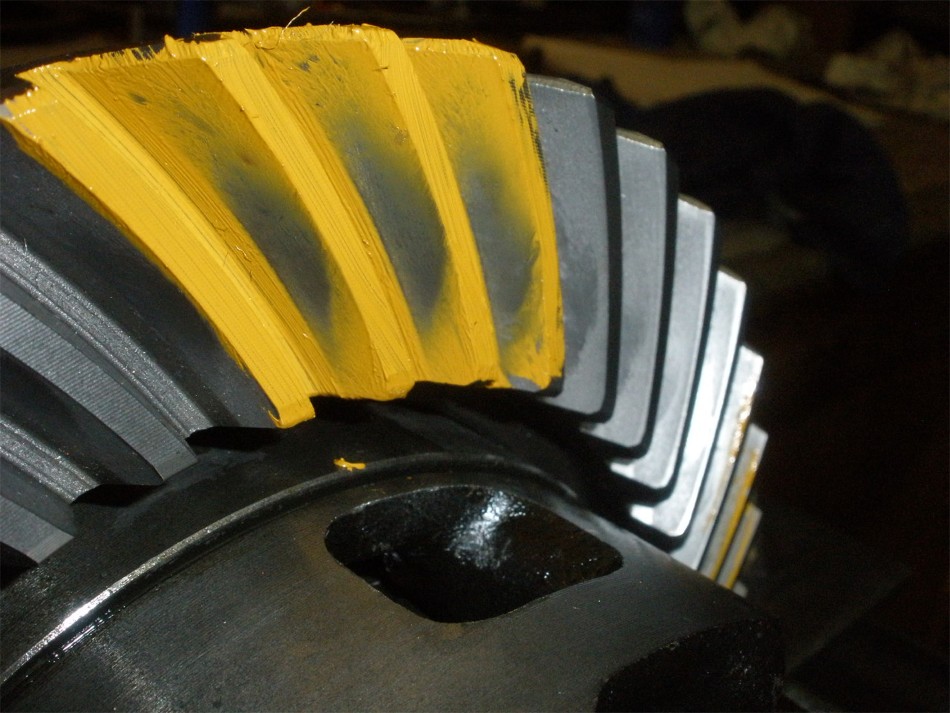
COAST---- I like the "center to toe" favoring of the pattern for sure. |
|
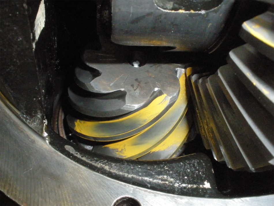
DRIVE on the pinion----slight shallow. |
|
DRIVE--- reverse painted. |
|
COAST--- reverse paint |
|
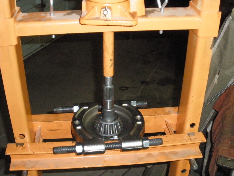
Now to press the pinion out to change the shim to something a touch more shallow. |
|
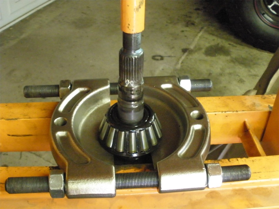
The bearing separator properly captures the bearing for removal with no chance of damage. |
|
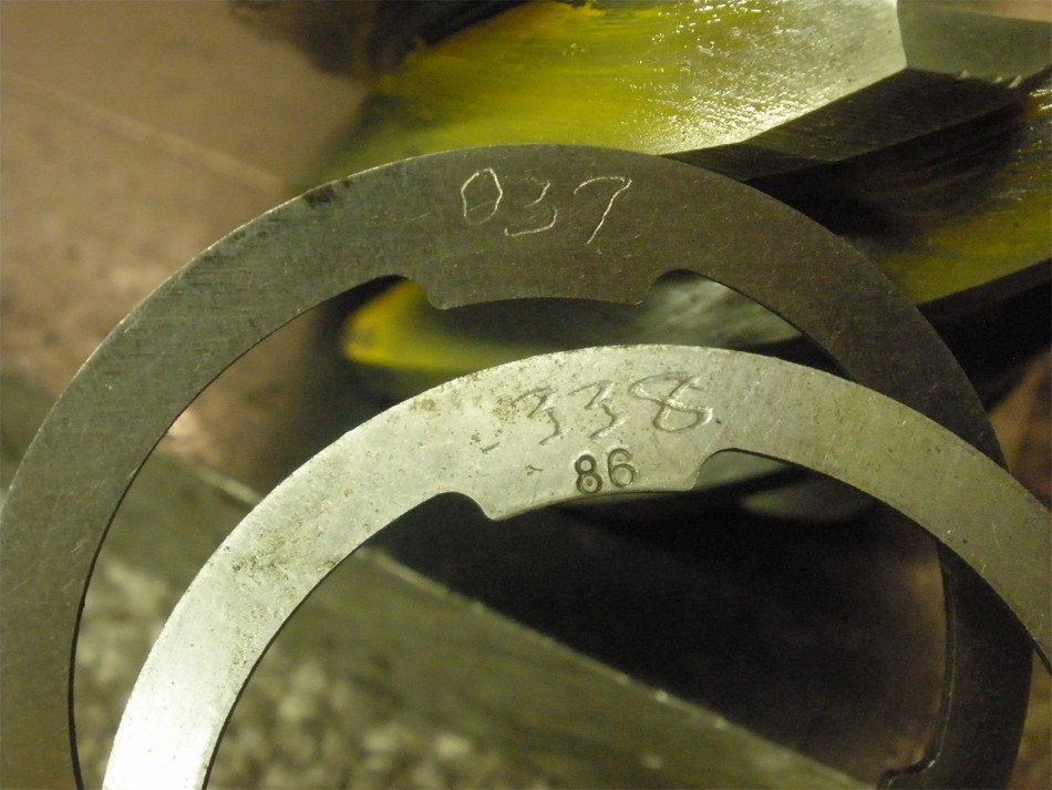
.039 plus .0338 equals .0728 My notes rounded to 072 but 0728 is the reality....that's .0037" more shallow than before. |
|
The 12ton press really does get used alot.....100 bucks well spent. |
|
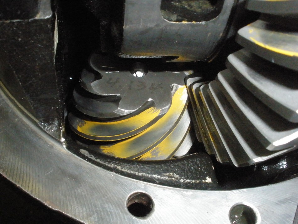
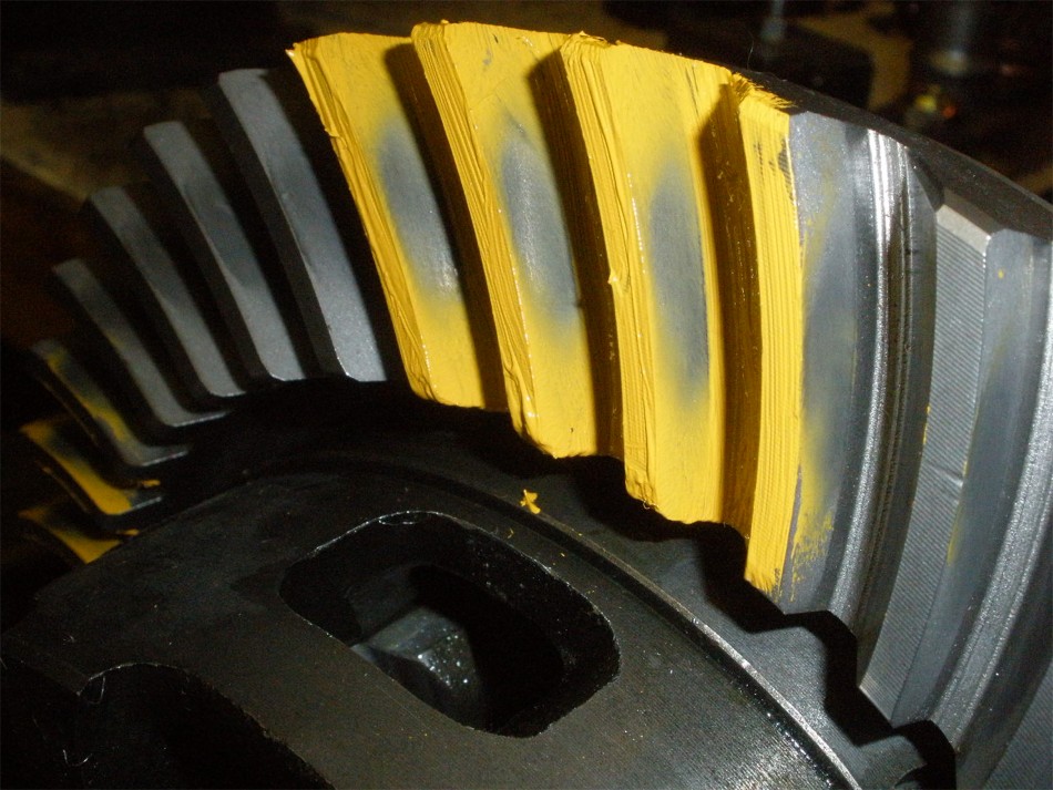
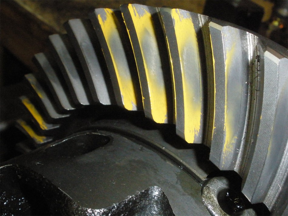
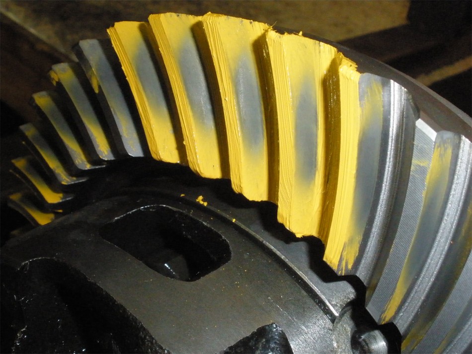
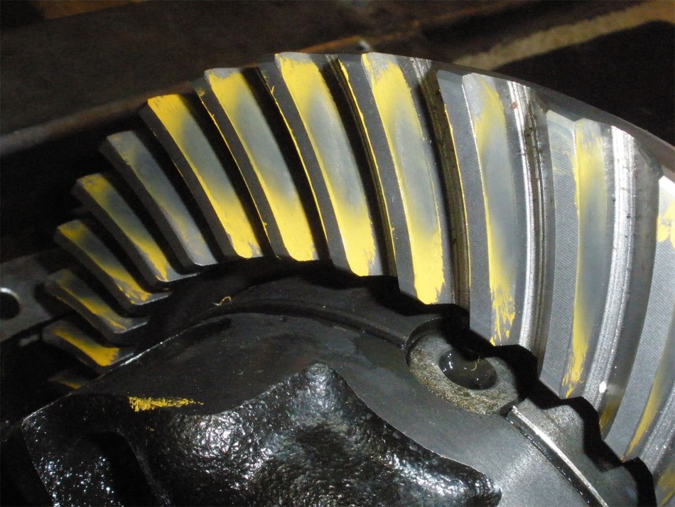
DRIVE--- perfect depth. |
|
COAST--- nice...I really like that the pattern favors the toe slightly. |
|
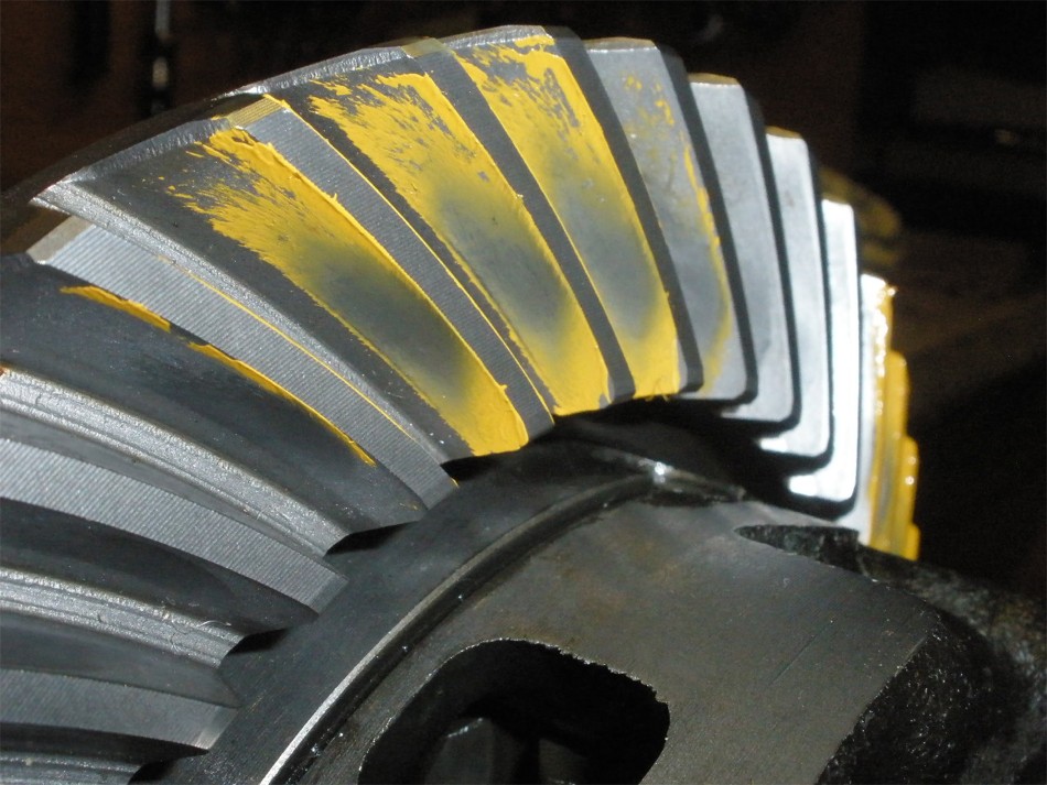
Pinion drive----excellent balance from face to flank. |
|
drive--- reverse painted. |
|
Coast---reverse painted |
|
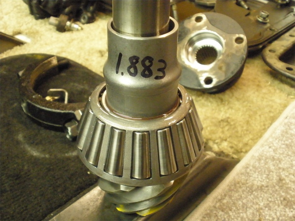
I know that the V6 e-locker 3rds require a crush sleeve of final dimensions of about 1.865" so I sometimes trim the sleeves closer to the final numbers to make the crush operation go faster...and save on thread tearing. |
|
Grease on the tension spring and rtv on the outside. |
|
.... |
|
Red Loctite and clean threads. |
|
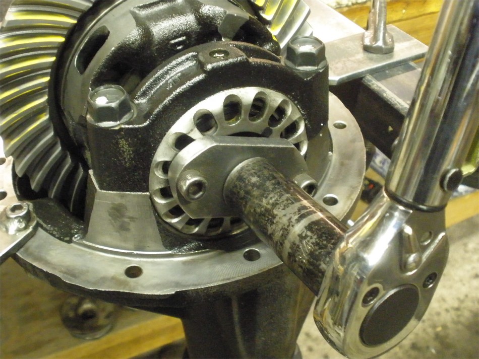
With the flange securely clamped, crushing the sleeve is an easy matter with the 4 foot cheater bar. |
|
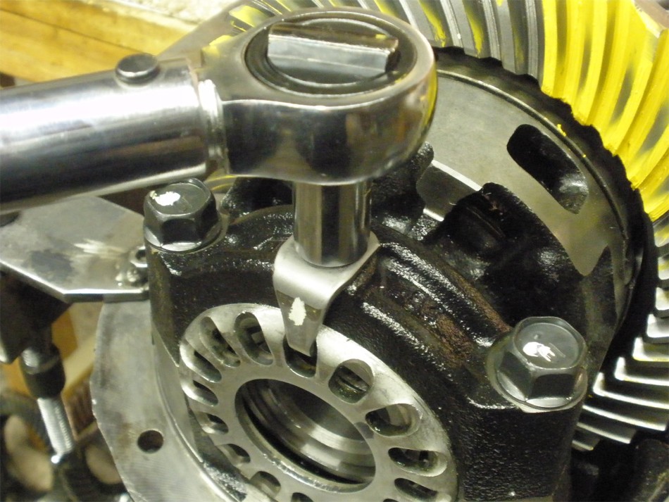
PPL is measured. |
|
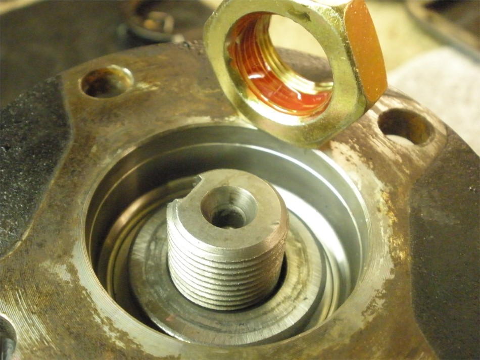
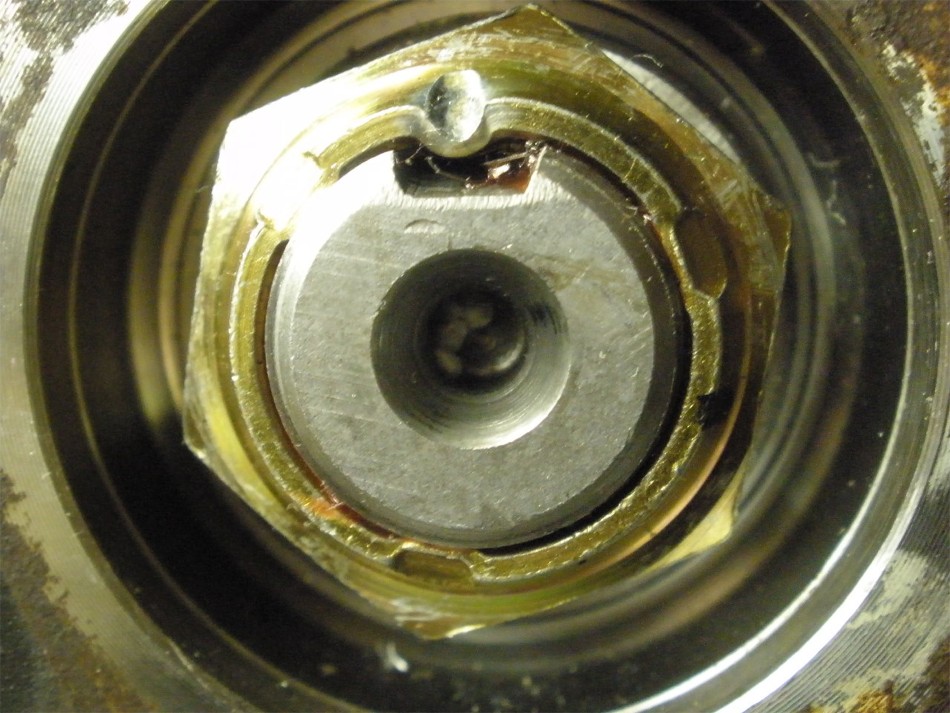
This particular pinion nut was a little different. It had 3 equally spaced dents that are designed to prevent it from ever coming loose. It's an interference thread fit at the outer ends of the nut. Between the ding I did and the red Loctite I would imagine the next guy is gonna have to give it "his all" to break it loose. :) |
|
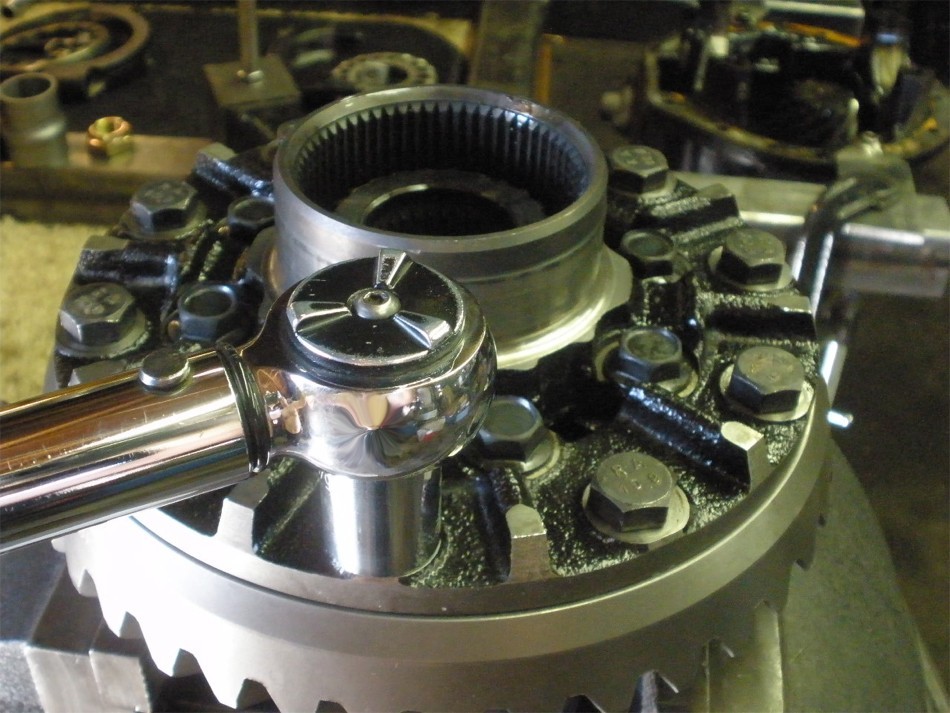
Bearing cap bolts are verified to be 75 ft/lb. |
|
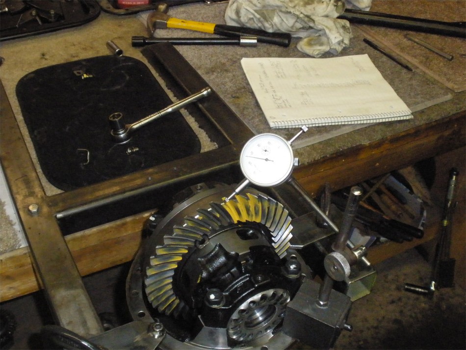
Carrier bearing preload is dialed in while guiding the backlash to the desired value(.007" in this case). |
|
Backlash is checked on every other tooth and recorded. |
|
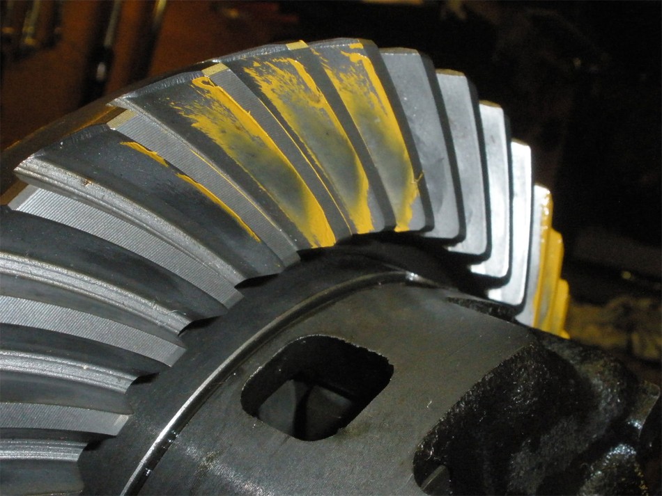
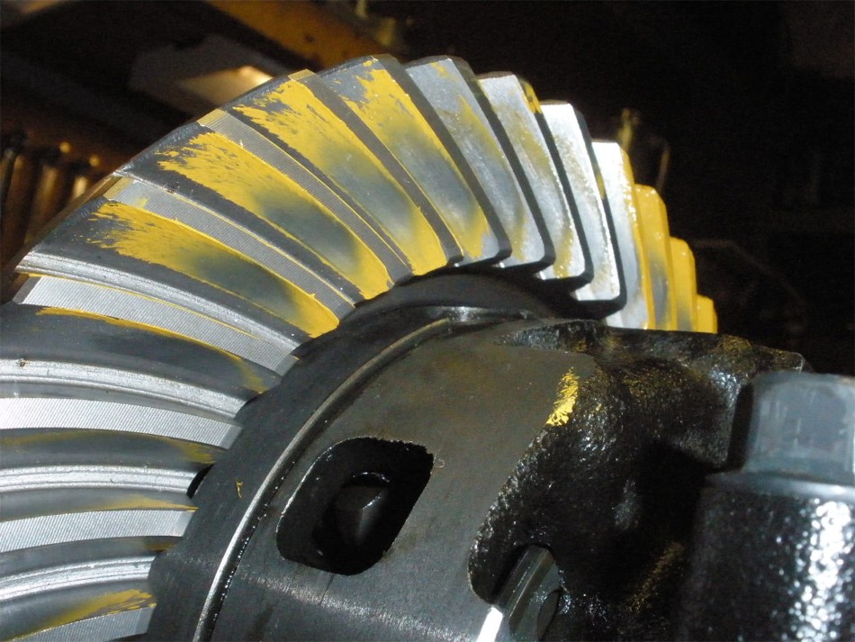
One more final check....drive |
|
Coast |
|
Drive on the pinion tooth |
|
drive--- reverse painted |
|
Coast--- reverse painted. |
|
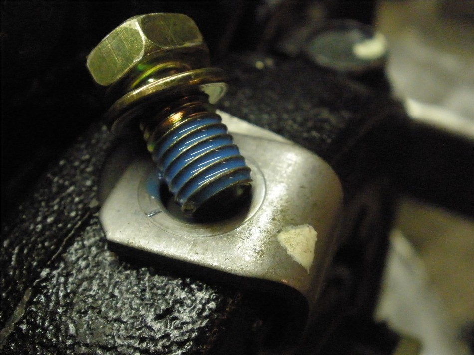
Blue loctite on the lock tab bolts. |
|
10 ft/lb. |
|
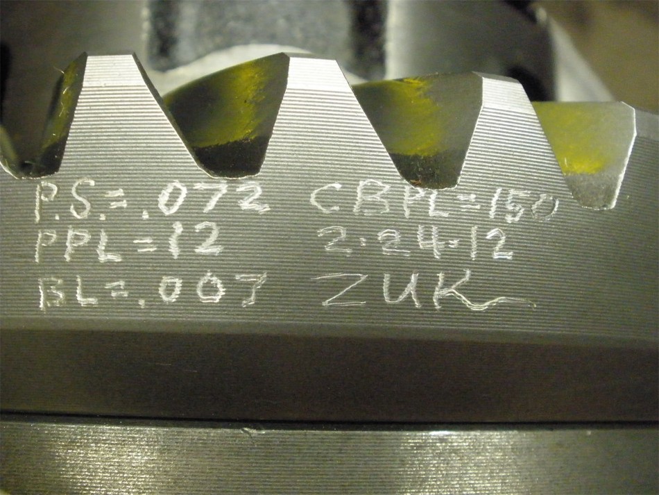
Date coded |
|
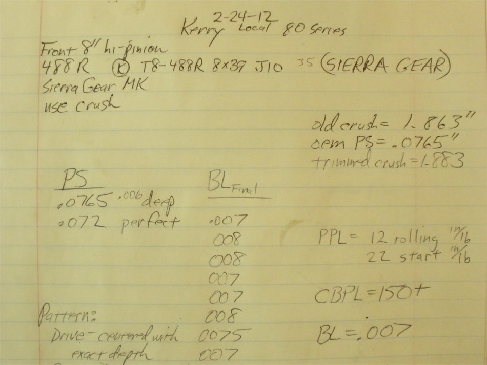
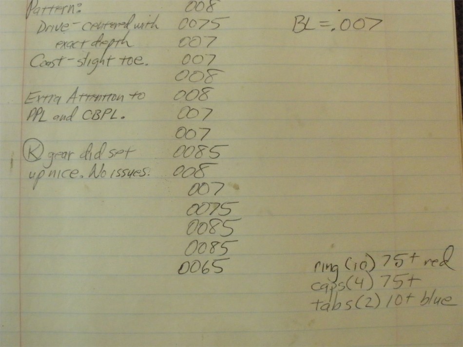
Notes of the install... |
|
Done :) |

|
